Controller matrix traces
Now why would these be interesting?
To enable people to recycle or simply improve the stuff they have! Make your own mechanical G15 for instance. However using the same matrix will result in exactly the same key rollover as the original, and using a different matrix on a non-reprogrammable controller will result in a keyboard with output that will need software remapping to function as desired.
Cherry MX[edit | edit source]
Filco Majestouch[edit | edit source]
Tested units[edit | edit source]
All product and revision numbers written as they appear on the units. Do not alter to make them "uniform".
| Keyboard model | Product number | Main PCB | Daughter PCB | LED color | LED resistor value |
|---|---|---|---|---|---|
| Filco Majestouch | MODEL/N. FKBN105M/SWB S/N. F10110012 |
FILCO FKB/N-104/5/6 PCBA Rev 1.0 (CST-FKB/N-104/5/6 Main PCBA Rev 1.0) 2010-03-23 |
(CST-Daughter PCBA Rev 3.1 ESD) 2010-08-24 |
10kΩ | |
| Filco Majestouch Linear R | Model No.: FILCK15 Part No.: FKBN104MR/EB2 Serial No.: 110200521 |
(CST-F104/5/6/8 Main PCB Rev 2.1) 2010-11-08 |
(CST-Daughter PCBA Rev 3.1 ESD) 2010-08-24 |
510Ω | |
| Filco Majestouch 2 Swedish Layout Red case with red switches |
Model No. FILCKF15 Part No. FKBN105MRL/SWR2 Serial No. 121000007 |
(CST-F104/5/6/8 Main PCB Rev 3.0) 2012-03-24 |
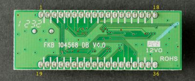
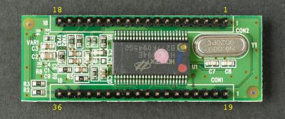
FKB 104568 DB V4.0 | Red | 510Ω |
| Filco Majestouch 2 US Layout Blue case with brown switches |
Model No. FILCKF15 Part No. FKBN104M2-AI Serial No. 120600077 |
(CST-F104/5/6/8 Main PCB Rev 3.0) 2012-03-24 |
FKB 104568 DB V4.0 | Blue | 10kΩ |
Physical dimensions[edit | edit source]
PCB dimensions: 50 mm × 18 mm
Pin configuration: 2 rows of 18 pins each, 15 mm apart, 2 mm pin pitch.
Pinout and matrix[edit | edit source]
| Non-matrix pins | |
|---|---|
| 12 | USB Ground |
| 13 | USB D+ |
| 14 | USB D- |
| 15 | ? |
| 16 | ? |
| 17 | ? |
| 18 | USB +5V |
| 34 | LED Num Lock |
| 35 | LED Caps Lock |
| 36 | LED Scroll Lock |
| Col | 0 | 1 | 2 | 3 | 4 | 5 | 6 | 7 | |
|---|---|---|---|---|---|---|---|---|---|
| Row | Pin# | 1 | 20 | 22 | 23 | 29 | 31 | 32 | 33 |
| A | 2 | no | RCTL | no | no | LCTL | BRK | no | F5 |
| B | 3 | F12 | ENT | BSPC | BSLS | F9 | no | F11 | F10 |
| C | 4 | RALT | no | no | no | no | SLCK | LALT | PSCR |
| D | 5 | APP | DOT | F7 | L | F8 | O | no | 9 |
| E | 6 | no | COMM | RBRC | K | EQL | I | F6 | 8 |
| F | 7 | N | M | Y | J | 6 | U | H | 7 |
| G | 8 | B | V | T | F | 5 | R | G | 4 |
| H | 9 | no | C | F3 | D | F2 | E | F4 | 3 |
| I | 10 | no | X | CAPS | S | F1 | W | NUBS | 2 |
| J | 11 | no | Z | TAB | A | GRV | Q | ESC | 1 |
| K | 19 | DOWN | NLCK | P4 | P1 | DEL | P7 | SPC | no |
| L | 21 | RGHT | PSLS | P5 | P2 | INS | P8 | P0 | no |
| M | 24 | no | no | no | RGUI | no | no | no | no |
| N | 25 | no | no | LSFT | RSFT | no | no | no | no |
| O | 26 | LEFT | no | no | PENT | HOME | PPLS | UP | END |
| P | 27 | no | no | LGUI | no | no | no | no | no |
| Q | 28 | PMNS | PAST | P6 | P3 | PGUP | P9 | PDOT | PGDN |
| R | 30 | SLSH | no | LBRC | SCLN | MINS | P | QUOT | 0 |
Filco Majestouch TKL[edit | edit source]
Tested units[edit | edit source]
All product and revision numbers written as they appear on the units. Do not alter to make them "uniform".
| Keyboard model | Product number | Main PCB | Daughter PCB | LED color | LED resistor value |
|---|---|---|---|---|---|
| Filco Majestouch 2 TKL | Model No.: Part No.: Serial No.: |
CST-F87/88/89/91-MB V1.1 2010-11-09 |
Tenkeyless PCBA Rev 2.1-ESD | 10kΩ | |
| Filco Majestouch 2 TKL | Model No.:FILCKTL15 KCC-REI-FKB-FKBN87M Part No.: FKBN88M/SWB2 Serial No.: 110900256 |
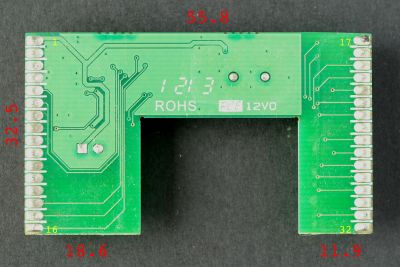
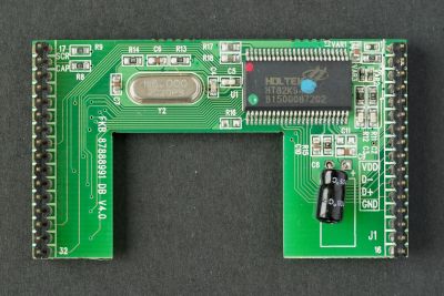
CST-F87/88/89/91-MB V1.1 | FKB 87888991 DB V4.0 | Blue | 10kΩ |
| HID Liberation Device | Revision 2012-09-11 | 10kΩ |
Physical dimensions[edit | edit source]
Pinout and matrix[edit | edit source]
| Non-matrix pins | |
|---|---|
| 1 | USB +5V |
| 2 | USB D- |
| 3 | USB D+ |
| 4 | USB Ground |
| 17 | LED Caps Lock |
| 18 | LED Scroll Lock |
| Col | 0 | 1 | 2 | 3 | 4 | 5 | 6 | 7 | |
|---|---|---|---|---|---|---|---|---|---|
| Row | Pin# | 29 | 31 | 26 | 30 | 19 | 21 | 24 | 22 |
| A | 25 | no | RCTL | no | no | LCTL | BRK | no | F5 |
| B | 5 | F12 | ENT | BSPC | BSLS | F9 | (J14) | F11 | F10 |
| C | 16 | (J133/ALT+R) | no | no | RALT | no | SLCK | LALT | PSCR |
| D | 7 | APP | DOT | F7 | L | F8 | O | no | 9 |
| E | 8 | (J56) | COMM | RBRC | K | EQL | I | F6 | 8 |
| F | 9 | N | M | Y | J | 6 | U | H | 7 |
| G | 10 | B | V | T | F | 5 | R | G | 4 |
| H | 11 | no | C | F3 | D | F2 | E | F4 | 3 |
| I | 12 | no | X | CAPS | S | F1 | W | (K45) | 2 |
| J | 13 | (J131) | Z | TAB | A | GRV | Q | ESC | 1 |
| K | 27 | DOWN | no | no | no | DEL | no | SPC | no |
| L | 28 | RGHT | no | no | no | INS | no | no | no |
| M | 32 | (J131_2) | no | no | RGUI | no | no | no | no |
| N | 14 | no | no | LSFT | RSFT | no | no | no | no |
| O | 23 | LEFT | no | no | no | HOME | no | UP | END |
| P | 15 | no | no | LGUI | no | no | no | no | no |
| Q | 20 | no | no | no | no | PGUP | no | no | PGDN |
| R | 6 | SLSH | no | LBRC | SCLN | MINS | P | QUOT | 0 |
Phantom[edit | edit source]
(picture to be)
Tested units[edit | edit source]
| Keyboard model | Product number | Main PCB | Daughter PCB |
|---|---|---|---|
| Phantom | Revision: 2011-12-19 | Teensy 2.0 |
Physical dimensions[edit | edit source]
Pinout and matrix[edit | edit source]
| Non-matrix pins | |
|---|---|
| B6 | LED Caps Lock |
| B7 | LED Scroll Lock |
| Pin # | B0 noWin | B0 Win | B1 | B2 | B3 | B4 | B5 |
|---|---|---|---|---|---|---|---|
| D5 | LCTL | LCTL | LSFT | CAPS | TAB | 1 | ESC |
| C7 | LGUI | LGUI | NUBS | A | Q | 2 | GRV |
| C6 | LALT | LALT | Z | S | W | 3 | F1 |
| D4 | NO | NO | X | D | E | 4 | F2 |
| D0 | NO | NO | C | F | R | 5 | F3 |
| E6 | NO | NO | V | G | T | 6 | F4 |
| F0 | NO | NO | B | H | Y | 7 | F5 |
| F1 | SPC | SPC | N | J | U | 8 | F6 |
| F4 | NO | NO | M | K | I | 9 | F7 |
| F5 | NO | NO | COMM | L | O | 0 | F8 |
| F6 | NO | RALT | DOT | SCLN | P | MINS | F9 |
| F7 | RALT | RGUI | SLSH | QUOT | LBRC | EQL | F10 |
| D7 | APP | APP | NO | BSLS | RBRC | NO | F11 |
| D6 | RCTL | RCTL | RSFT | ENT | BSLS | BSPC | F12 |
| D1 | LEFT | LEFT | NO | NO | DEL | INS | PSCR |
| D2 | DOWN | DOWN | UP | NO | END | HOME | SLCK |
| D3 | RGHT | RGHT | NO | NO | PGDN | PGUP | BRK |
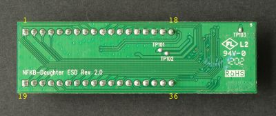
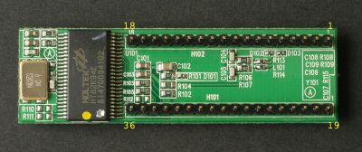
Rosewill[edit | edit source]
Tested units[edit | edit source]
All product and revision numbers written as they appear on the units. Do not alter to make them "uniform".
| Keyboard model | Product number | Main PCB | Daughter PCB | LED color | LED resistor value |
|---|---|---|---|---|---|
| Rosewill RK-9000 | RK-9000RE | (CST-NFK104/5/6/8 Main PCB Rev 3.0) 2011-06-28 |
NFKB-Daughter ESD Rev 2.0 | Blue | 10kΩ |
| Rosewill RK-9000 | RK-9000BL | Nashville 104568 MB V5.0 2012-06-18 |
NFKB-Daughter ESD Rev 2.0 | Blue | 10kΩ |
| Rosewill RK-9000 | RK-9000BR | NashVille_104568_MB_V6.0_20130620 | NFKB-Daughter ESD Rev 2.0 | Blue | 10kΩ |
Physical dimensions[edit | edit source]
PCB dimensions: 56 mm × 17 mm.
Pin configuration: 2 rows of 18 pins each, 12 mm apart, 2 mm pin pitch.
Pinout and matrix[edit | edit source]
| Non-matrix pins | |
|---|---|
| 5 | USB D- |
| 6 | USB D+ |
| 14 | USB Ground |
| 15 | USB Ground |
| 16 | USB Ground |
| 17 | USB Ground |
| 18 | USB +5V |
| 34 | LED Num Lock |
| 35 | LED Caps Lock |
| 36 | LED Scroll Lock |
| Col | 0 | 1 | 2 | 3 | 4 | 5 | 6 | 7 | |
|---|---|---|---|---|---|---|---|---|---|
| Row | Pin# | 1 | 20 | 22 | 23 | 29 | 31 | 32 | 33 |
| A | 2 | no | RCTL | no | no | LCTL | BRK | no | F5 |
| B | 3 | F12 | ENT | BSPC | BSLS | F9 | no | F11 | F10 |
| C | 4 | RALT | no | no | no | no | SLCK | LALT | PSCR |
| D | 7 | APP | DOT | F7 | L | F8 | O | no | 9 |
| E | 8 | no | COMM | RBRC | K | EQL | I | F6 | 8 |
| F | 9 | N | M | Y | J | 6 | U | H | 7 |
| G | 10 | B | V | T | F | 5 | R | G | 4 |
| H | 11 | no | C | F3 | D | F2 | E | F4 | 3 |
| I | 12 | no | X | CAPS | S | F1 | W | NUBS | 2 |
| J | 13 | no | Z | TAB | A | GRV | Q | ESC | 1 |
| K | 19 | DOWN | NLCK | P4 | P1 | DEL | P7 | SPC | no |
| L | 21 | RGHT | PSLS | P5 | P2 | INS | P8 | P0 | no |
| M | 24 | no | no | no | RGUI | no | no | no | no |
| N | 25 | no | no | LSFT | RSFT | no | no | no | no |
| O | 26 | LEFT | no | no | PENT | HOME | PPLS | UP | END |
| P | 27 | no | no | LGUI | no | no | no | no | no |
| Q | 28 | PMNS | PAST | P6 | P3 | PGUP | P9 | PDOT | PGDN |
| R | 30 | SLSH | no | LBRC | SCLN | MINS | P | QUOT | 0 |
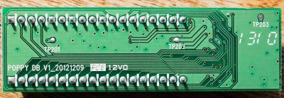
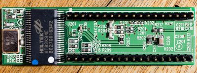
CM Storm QuickFire XT[edit | edit source]
Note: Pin numbers are the same as on the Rosewill controller board.
Tested units[edit | edit source]
All product and revision numbers written as they appear on the units. Do not alter to make them "uniform".
| Keyboard model | Product number | Main PCB | Daughter PCB | LED color | LED resistor value |
|---|---|---|---|---|---|
|
CM Storm QuickFire XT |
SGK-4030-GKCG1-US | POPPY 1045678 MB V2_20130204 | POPPY DB V1_20121209 | Red | 510 (3x), 1k (Win LED) |
Physical dimensions[edit | edit source]
PCB dimensions: 56 mm × 17 mm.
Pin configuration: 2 rows of 18 pins each, 12 mm apart, 2 mm pin pitch.
Pinout and matrix[edit | edit source]
| Non-matrix pins | |
|---|---|
| 5 | USB Ground |
| 6 | USB +5V |
| 7 | USB Ground |
| 8 | USB D- |
| 9 | USB D+ |
| 10 | USB Ground |
| 19 | LED Win Lock (-) |
| 34 | LED Num Lock (-) |
| 35 | LED Caps Lock (-) |
| 36 | LED Scroll Lock (-) |
| Col | 0 | 1 | 2 | 3 | 4 | 5 | 6 | 7 | |
|---|---|---|---|---|---|---|---|---|---|
| Row | Pin# | 16 | 17 | 29 | 28 | 27 | 1 | 14 | 30 |
| A | 2 | no | RCTL | no | no | LCTL | BRK | no | F5 |
| B | 24 | F12 | ENT | BSPC | BSLS | F9 | no | F11 | F10 |
| C | 20 | RALT | no | no | no | no | SLCK | LALT | PSCR |
| D | 23 | APP | DOT | F7 | L | F8 | O | no | 9 |
| E | 22 | no | COMM | RBRC | K | EQL | I | F6 | 8 |
| F | 25 | N | M | Y | J | 6 | U | H | 7 |
| G | 26 | B | V | T | F | 5 | R | G | 4 |
| H | 21 | no | C | F3 | D | F2 | E | F4 | 3 |
| I | 4 | no | X | CLCK | S | F1 | W | NUBS | 2 |
| J | 3 | no | Z | TAB | A | GRV | Q | ESC | 1 |
| K | 13 | DOWN | NLCK | P4 | P1 | DEL | P7 | SPC | no |
| L | 18 | RGHT | PSLS | P5 | P2 | INS | P8 | P0 | no |
| M | 31 | no | no | no | RGUI | no | no | no | no |
| N | 33 | no | no | LSFT | RSFT | no | no | no | no |
| O | 15 | LEFT | no | no | PENT | HOME | PPLS | UP | END |
| P | 32 | no | no | LGUI | no | no | no | no | no |
| Q | 11 | PMNS | PAST | P6 | P3 | PGUP | P9 | PDOT | PGDN |
| R | 12 | SLSH | no | LBRC | SCLN | MINS | P | QUOT | 0 |
Note: Pins 23 and 16 lead to the key switch where APP would be in the layout, but the original controller treats it exclusively as a private modifier, meaning no keycode is emitted when the key is pressed alone.
CM Storm Quick Fire Rapid/Stealth[edit | edit source]
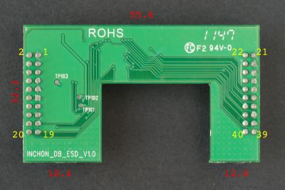
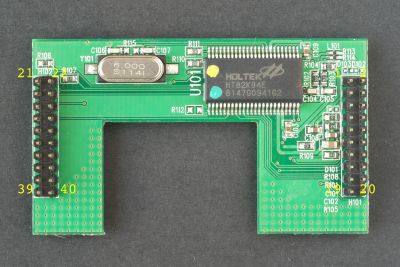
Note: The color coding on the Holtek controller of the QFS is white-green (QFR is green-yellow as shown.)
Tested units[edit | edit source]
All product and revision numbers written as they appear on the units. Do not alter to make them "uniform".
| Keyboard model | Product number | Main PCB | Daughter PCB | LED color | LED resistor value |
|---|---|---|---|---|---|
| CM Storm QFR | Model No.: Part No.: Serial No.: |
CST-IF87/88/89/91-MB V1.1 2011-07-26 |
INCHON_DB_ESD_V1.0 | Red | 510Ω |
| CM Storm QFS | SGK-4000-GKCL2-US | CST-IF87/88/89/91-MB V2 2012-07-30 |
INCHON_DB_ESD_V1.0 | Red | 510Ω |
| CM Storm QFR | SGK-4000-GKCM1-US | Quickfire_V2.2 | INCHON_DB_ESD_V1.0 | Red | 510Ω |
Physical dimensions[edit | edit source]
Pinout and matrix[edit | edit source]
| Non-matrix pins | |
|---|---|
| 1 | USB D- |
| 2 | USB D+ |
| 3 | USB +5V |
| 4 | USB Ground |
| 5 | LED Win Lock |
| 7 | USB Ground |
| 9 | USB Ground |
| 11 | USB Ground |
| 21 | LED Caps Lock |
| 23 | LED Scroll Lock |
| 25 | USB Ground |
| 27 | USB Ground |
| 29 | USB Ground |
| 33 | USB Ground |
| Col | 0 | 1 | 2 | 3 | 4 | 5 | 6 | 7 | ||
|---|---|---|---|---|---|---|---|---|---|---|
| Row | Pin# | 40 | 37 | 34 | 39 | 22 | 26 | 32 | 28 | |
| A | 31 | no | RCTL | no | no | LCTL | BRK | no | F5 | |
| B | 6 | F12 | ENT | BSPC | BSLS | F9 | no | F11 | F10 | |
| C | 13 | RALT | no | no | no | no | SCRL | LALT | PSCR | |
| D | 10 | DOT | F7 | L | F8 | O | no | 9 | ||
| E | 12 | no | COMM | RBRC | K | EQ | I | F6 | 8 | |
| F | 14 | N | M | Y | J | 6 | U | H | 7 | |
| G | 16 | B | V | T | F | 5 | R | G | 4 | |
| H | 18 | no | C | F3 | D | F2 | E | F4 | 3 | |
| I | 20 | no | X | CAPS | S | F1 | W | NUBS | 2 | |
| J | 19 | no | Z | TAB | A | GRV | Q | ESC | 1 | |
| K | 36 | DOWN | NUML | P4 | P1 | DEL | P7 | SPC | no | |
| L | 38 | RGHT | PSLS | P5 | P2 | INS | P8 | P0 | no | |
| M | 35 | no | no | no | RGUI | no | no | no | no | |
| N | 17 | no | no | LSFT | RSFT | no | no | no | no | |
| O | 30 | LEFT | no | PDOT | PENT | HOME | PPLS | UP | END | |
| P | 15 | no | no | LGUI | no | no | no | no | no | |
| Q | 24 | PMNS | PAST | P6 | P3 | PGUP | P9 | PSEP | PGDN | |
| R | 8 | SLSH | BSLS | LBRC | SCLN | MINS | P | QUOT | 0 |
Note: Pins 40 and 10 lead to the key switch where APP would be in the layout, but the original controller treats it exclusively as a private modifier, meaning no keycode is emitted when the key is pressed alone.
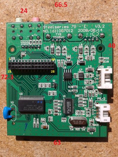
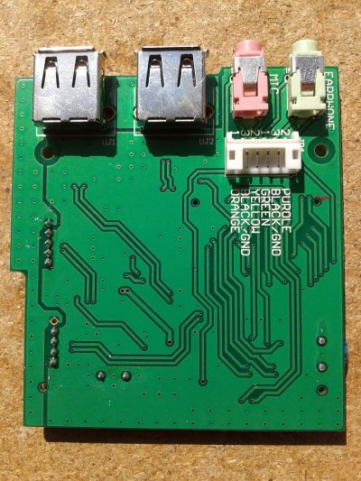
Steelseries 7G[edit | edit source]
Tested units[edit | edit source]
| Keyboard model | Main PCB | LED color | LED resistor value |
|---|---|---|---|
|
Steelseries 7G (US layout) |
Steelseries 7G - E V3.2 NO. 1611007012 2008-08-14 |
white | Doesn't seem to have resistors (PWM?) |
Physical dimensions[edit | edit source]
PCB dimensions: 66.5 mm × 72.3 mm
Pin configuration: 2 rows of 14 pins each, 2 mm apart, 2 mm pin pitch.
Pinout and matrix[edit | edit source]
| Non-matrix pins | |
|---|---|
| 4 | LED + |
| 5 | LED Num Lock - |
| 6 | LED Scroll Lock - |
| 7 | LED Caps Lock - |
| Pin # | 18 | 19 | 20 | 21 | 22 | 25 | 27 | 28 |
|---|---|---|---|---|---|---|---|---|
| 1 | RCTL | NO | NO | LCTL | CAPS | NO | NO | NO |
| 2 | Z | A | NO | Q | TAB | 1 | GRV | ESC |
| 3 | NO | NO | NO | NO | NO | LGUI | PENT | SCLK |
| 8 | P1 | P4 | PPLS | P7 | PAST | PSLS | APP | PSCR |
| 9 | PDOT | P6 | P3 | P9 | DEL | INS | F4 | F3 |
| 10 | P0 | P5 | P2 | P8 | END | HOME | F12 | F11 |
| 11 | X | W | S | 2 | PGDN | PGUP | F2 | F1 |
| 12 | DOT | LBRC | L | O | MINS | 9 | F8 | F7 |
| 13 | ENT | BSLS | LEFT | RBRC | BSPC | EQL | F6 | F5 |
| 14 | P | QUOT | SLSH | SCLN | DOWN | 0 | F10 | F9 |
| 15 | NO | LALT | RALT | NO | NO | NO | NLCK | PMNS |
| 16 | RSFT | NO | NO | LSFT | NO | NO | right NUBS * |
BRK |
| 17 | NO | NO | NO | left NUBS * |
RGUI | UP | SPC | RGHT |
| 23 | COMM | D | C | K | E | I | 8 | 3 |
| 24 | B | G | V | F | T | R | 5 | 4 |
| 26 | M | J | N | H | U | Y | 7 | 6 |
The left and right Non-US backslash keys places are present on the keyboard PCB. This is a little strange because the 105 key version of the 7G has only the left non-US backslash.
The controller contains the USB hub chip (Alcor AU9254A21-HBS-NP) and the USB power switch chip (AIC1526).
Rubber dome / membrane[edit | edit source]
G15[edit | edit source]
This has 5 membrane connectors, from left to right: J9, J2_1, J2_2, J3_1 and J3_2; of which the _1's are for the top sheet, and the _2's for the bottom one. The pinout on those is clearly labeled, but noted here for reference:
Connectors:[edit | edit source]
| J2_1 | GS1 | GS3 | GS5 | GS6 | GS4 | GS2 | GS0 | GS7 | ||||||||
| J2_2 | GR0 | GR6 | GR4 | GR2 | GR1 | GR3 | GR5 | GR7 | R10 | R11 | R12 | R13 | R14 | R15 | R16 | R17 |
| J3_1 | S0 | S1 | S2 | S3 | S4 | S5 | S6 | S7 | S8 | S9 | S10 | S11 | ||||
| J3_2 | R0 | R1 | R2 | R3 | R4 | R5 | R6 | R7 | R8 | R9 |
J9 Is not marked. Is connected to the 4 buttons above the G-keys: page 1/2/3 and record.
And here are the traces as they are on the membrane, from connector to end of the line (approximately since some do split):
Traces:[edit | edit source]
J3_2[edit | edit source]
| R0 | 2 | x | LShiftLEFT | SpaceMID |
|---|---|---|---|---|
| R1 | w | s | LCtrl | |
| R2 | 3 | e | d | LWin |
| R3 | 4 | r | c | LAlt |
| R4 | 5 | t | f | v |
| R5 | y | h | g | b |
| R6 | 6 | u | n | RAlt |
| R7 | 7 | j | RWin | |
| R8 | i | m | . | RCtrl |
| R9 | k | / | RShiftRIGHT | EnterRIGHT |
J2_2[edit | edit source]
| GR0 | G1 | G13 | backlight | |||||||||
|---|---|---|---|---|---|---|---|---|---|---|---|---|
| GR6 | G12 | |||||||||||
| GR4 | G10 | G17 | G5 | |||||||||
| GR2 | G3 | G15 | G8 | |||||||||
| GR1 | G2 | G7 | G14 | |||||||||
| GR3 | G4 | G9 | G16 | |||||||||
| GR5 | G6 | G11 | ||||||||||
| GR7 | G18 | |||||||||||
| R10 | 1 | q | a | z | ||||||||
| R11 | F3 | F2 | F1 | Esc | LShiftRIGHT | CapsLock | Tab | ` | n+BOT | n* | n/ | NumLock |
| R12 | F4 | F5 | F6 | F7 | SpaceLEFT | SpaceRIGHT | AppKey | |||||
| R13 | ArrDown | n9 | n6 | n3 | PauseBreak | F12 | BackspaceRIGHT | Delete | = | |||
| R14 | ArrUp | n+TOP | n1 | n4 | n7 | PageUp | Home | Insert | ScrollLock | \ | BackspaceLEFT | |
| R15 | End | PageDown | ArrRight | n0LEFT | n0RIGHT | n2 | n5 | n8 | n. | - | 0 | |
| R16 | 9 | 8 | ArrLeft | ] | [ | p | o | Mute | Printscreen | n- | nEnterTOP | nEnterBOT |
| R17 | F8 | F9 | F10 | F11 | EnterLEFT | RShiftLEFT | ' | ; | l | , |
J3_1[edit | edit source]
| S0 | F8 | - | 8 | i | n4 | F4 | F2 | 3 | LShiftLEFT | |||
|---|---|---|---|---|---|---|---|---|---|---|---|---|
| S1 | F9 | BackspaceRIGHT | n7 | EnterRIGHT | 0 | 9 | F5 | 4 | 2 | F1 | LCtrl | |
| S2 | F10 | = | BackspaceLEFT | n5 | \ | o | 5 | F6 | w | 1 | Esc | LWin |
| S3 | F11 | n8 | Insert | Delete | p | y | e | F3 | F7 | LAlt | ||
| S4 | n6 | Home | End | [ | l | 6 | r | t | ` | SpaceLEFT | ||
| S5 | n9 | n2 | PageUp | ] | ' | 7 | g | f | Tab | x | ||
| S6 | F12 | n1 | PageDown | ArrLeft | ; | . | RAlt | SpaceRIGHT | h | s | CapsLock | |
| S7 | Printscrn | n3 | n. | ArrUp | EnterLEFT | RWin | k | u | d | LShiftRIGHT | ||
| S8 | ScrollLock | NumLock | n- | n0LEFT | n0RIGHT | ArrDown | RCtrl | , | j | c | q | |
| S9 | PauseBreak | n/ | n+TOP | nEnterTOP | nEnterBOT | ArrRight | AppKey | RShiftLEFT | RShiftRIGHT | m | v | |
| S10 | Mute | n* | / | b | a | |||||||
| S11 | n+BOT | SpaceMID | n | z |
J2_1[edit | edit source]
| GS1 | G2 | G8 | |
|---|---|---|---|
| GS3 | G4 | G10 | G14 |
| GS5 | G6 | G12 | G16 |
| GS6 | G18 | G17 | |
| GS4 | G15 | G11 | G5 |
| GS2 | G13 | G9 | G3 |
| GS0 | G7 | G1 | |
| GS7 | backlight |
Proper matrix:
n/a (yet?)
|